A simple direct conversion receiver from available (modern) parts. A simple direct conversion receiver from available (modern) parts Direct conversion receiver using three Polyakov transistors
I'm building a simple PPP
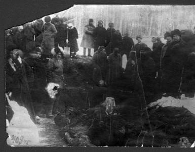
Recently, my eight-year-old son decided to “get involved with the soldering iron” and asked to make some kind of receiver with him. Taking into account the fact that the only instruments at home are a Chinese digital multimeter, my choice fell on the already legendary PPP V.T. Polyakov. I already made this receiver back in 1980, and it only left Nice memories. But in those years I had neither experience nor normal instruments and, naturally, no instrumental measurements were carried out - it worked and okay. And now it was difficult to resist the temptation to repeat this design and test it with instruments, but the main thing is to compare its sound with my PPPwhen working on the same desktop on the same antenna (10-12m wires at a height of 10-12m) on the 40m range - the most difficult for IFR in terms of interference, because powerful broadcast radio stations are very close in frequency, and if the receiver works well on this range, it will work without problems on all the others. Moreover, I was interested in the PPP version specifically on germanium transistors (albeit already outdated - but many radio amateurs have had half a bucket of them in their bedside tables since time immemorial), because The author has already come across statements from colleagues several times that they supposedly provide a softer sound to receivers or simply ULF. And so, without undue haste, in two evenings, my little son (under my strict guidance) soldered the receiver, checked the modes, took a couple more minutes to adjust the GPA and, holding our breath, connected the antenna (Fig. 1).
Alas, it is evening time (it was in February, 22-00 Moscow time), there is practically no passage and throughout the entire range in the headphones you can only hear deafening whistles, noises and... a Chinese broadcaster. In the morning, before leaving for work, we turned on the PPP again. The passage was good, the amateur stations sounded loud and sometimes deafening, but the sound was somehow ringing, compressed in the spectrum and very unpleasant to the ear. And again, almost over the entire range, the above-mentioned broadcaster was audible, albeit much quieter. The boy's disappointment knew no bounds, and I had an urgent need to carefully analyze this, in general, simple design and look for ways to optimally configure it at home, in fact, having only a cheap tester and an ordinary broadcast receiver (in this case ISHIM- 003) as a control, as well as possible ways to improve the main parameters.
Judging by the messages that appear from time to time on various forums, a large number of novice radio amateurs are faced with similar problems. As a result of these thoughts, this article appeared, the main task of which is to tell a novice radio amateur in detail how to make and correctly configure a simple PPP at home.
 So, let's begin. In view of the fact that we only have a Chinese digital multimeter DT-830B among measuring instruments, in order to optimally configure the circuit and correctly understand the processes occurring in it, we need to carry out certain preliminary preparations and try to obtain maximum information about the parameters of the main parts (this, as we will see further, in the future it will be very useful to us when analyzing the operation of the circuit and finding ways to improve its operation). Let's start selecting the main parts.
1. Transistors. As indicated in the description, almost any low-frequency pnp transistors are suitable for a low-frequency amplifier. It is desirable, however, that V3 be low-noise (P27A, P28, MP39B), and the current transfer coefficient of both transistors is not lower than 50-60. Having switched the multimeter to the mode for measuring the base current transfer coefficient (the names Vst, N21e are also used), we carry out measurements (Fig. .2) and select the required ones from the available copies. It should be noted that the results of these measurements should be treated as indicative, since a large error is possible, especially for germanium transistors. The peculiarity of this mode for the DT-830B multimeter (and similar Chinese ones) is that the measurement is carried out when a fixed current of 10 μA is applied to the base. Some examples of germanium transistors may have a collector-base reverse current of comparable magnitude, which leads to a proportional increase in readings. But in our case this is not critical.
2. Diodes for the mixer can be any high-frequency silicon from the KD503,509, 512, 521,522 series, but imported 1N4148 and similar ones are better. They are available and cheap ($0.01), but the main advantage is a significantly smaller range of parameters compared to domestic ones. It is advisable to pair them, although by direct resistance, by turning on the DT-830V multimeter in diode testing mode. The photo (Fig. 3) shows the result of testing and selecting more than fifty 1N4148 diodes. As you can see, their spread in direct resistance is extremely small, which, by the way, allows us to safely recommend them for constructing multi-diode mixers. For comparison, in order to select a pair of domestic KD522 with more or less similar values, I had to go through a good 2 dozen diodes.
3. The KPI can be anything, but it must be with an air dielectric, otherwise it will be difficult to obtain acceptable stability of the GPA. KPIs from VHF blocks of old industrial receivers (Fig. 4), which are still often found in our radio markets, are very convenient. They have a built-in 1:3 verner, which makes tuning to an SSB station much easier. By connecting both sections in parallel, we get a capacitance of approximately 8-34pF.
 To be specific, we will assume that we have such a KPI. If the maximum capacity of your KPI is different, it can be easily brought to the required value by connecting a 39-51pF stretching capacitor in series.
The calculation of a stretch capacitor is quite simple. The total, or equivalent, capacitance of series-connected capacitors Seq = (Skpe*Srast)/(Skpe+Srast).
From here, through several substitutions of trial values, you can obtain the desired value. So, with the maximum capacity of the KPI, for example, from Spidola = 360pF, let us need to obtain the equivalent capacity of the KPI (from the previous example = 34pF). By substituting the test values we find 39pF.
4. Electromagnetic headphones, always high-resistance (with electromagnet coils with an inductance of approximately 0.5 H and a direct current resistance of 1500...2200 Ohms), for example, types TON-1, TON-2, TON-2m, TA-4, TA- 56m. When connected in series, that is, the “+” of one is connected to the “-” of the other, they have a total resistance for direct current of 3.2-4.4 kOhm, for alternating current about 10-12 kOhm at a frequency of 1 kHz. Since they are included in the original PPP scheme from RA3AAE, it makes sense to leave them that way. In my version, the TON-2 phones are connected in parallel, which at one time made it possible to get a higher volume when working with Radio-76, since the resistance is 4 times less (both for direct current 800-1.1 kOhm and alternating current - approximately 3.5-4 kOhm), which, accordingly, provided a 4-fold increase in output power. I didn’t change it to sequential switching anymore - it’s not critical, but as experience has shown, the resulting volume is still excessive and it’s better, for this PPP, to use sequential switching of phones.
5. Low-pass filter inductor. As indicated in the article, the L3 low-pass filter coil with an inductance of 100 mH is wound on a K18X8X5 magnetic core made of 2000NN ferrite and contains 250 turns of PELSHO 0.1-0.15 wire. You can use a magnetic core K10Х7Х5 from the same ferrite, increasing the number of turns to 300, or K18Х8Х5 from ferrite 1500NM or 3000NM (in this case the winding should consist of 290 and 200 turns, respectively). You can also use a suitable ready-made one, for example, using half of the primary winding of the output transformer from small-sized transistor receivers or one of the windings of the universal magnetic heads of a cassette recorder. I used a ready-made 105mm coil from a disassembled industrial low-pass filter D3.4. IN as a last resort The filter coil can be replaced with a resistor with a resistance of 1-1.3 kOhm. But it’s still better to avoid this, because the selectivity and sensitivity of the receiver are already not very high, and in this case they will noticeably deteriorate.
6. HF to inductors (PDF and GPA). Special attention should be paid to these inductors, since a lot depends on their quality: receiver sensitivity, local oscillator frequency stability, selectivity. And as the experience of communication on forums shows, it is their production that causes the greatest difficulties for beginning radio amateurs, because It is unlikely that you will be able to get (purchase) the same frames as the author’s, or you will want to rebuild the receiver to a different range. In this matter, having an inductance meter, at least a simple attachment, would greatly help.
but we, as we previously agreed, have nothing except a multimeter and a household radio broadcast receiver with a HF band - one or several extended - not critical, for me it’s Ishim-003. How, in this case, to correctly select (calculate) and manufacture coils?
First of all, let me remind you that the resonant frequency of the circuit is determined by the well-known Thomson formula
Where F is frequency in MHz, L - inductance in μH, C -capacitance in pF
For each resonant frequency, the product L*C is a constant value, knowing it it is not difficult to calculate L with a known C and vice versa. So for the middle of the amateur bands, the product L * C (μH * pF) is equal to 28 MHz - 32.3, for 21 MHz - 57.4, for 14 MHz - 129.2, for 7 MHz - 517, for 3.5 MHz - 2068, for 1 ,8 MHz – 7400. The choice of specific values of L and C is quite arbitrary within certain limits, but in amateur practice there is a good, time-tested rule - for the 28 MHz range, take an inductance of about 1 μH, and a capacitance, respectively, of about 30 pF. As the frequency decreases, we increase in direct proportion to the capacitance of the capacitor and the inductance of the coil. So for a frequency of 7 MHz (input circuit) the recommended values are 120 pF and 4.3 μH, and for 3.5 MHz (GPA circuit) 240 and 8.6 μH.
But in practice, often, in particular for the scheme under discussion, large variations in values are permissible - by several times, without a noticeable effect on the quality of work. And often, quite prosaic things become the determining criterion:
1. Availability of ready-made coils with inductance close to the required values. As a rule, a radio amateur’s “bedside table” contains a couple of old, broken receivers, which serve as “donors” and suppliers of parts for new designs, incl. and coils, many of which can be suitable ready-made, without modifications, for our receiver. Since we do not have the ability to measure inductance, we can look for reference data - most likely in reference books on household equipment, previously published in mass quantities. Now on the Internet there are very effective search engines, so it’s not a problem to find such reference books in electronic form.
The main requirement when selecting ready-made coils is the presence of a tap (or coupling coil) from 1/3...1/4 (uncritical) of the turns. So the old “Sonata” served as the “donor” for my PPP. In the GPA I installed a KV-2 local oscillator circuit with an inductance of 3.6 µH (26.5 turns of a loop coil and 8 turns of a coupling coil), and in the input circuit I installed, in the absence of a more suitable one, a KV-4 coil with an inductance of 1.2 µH (15 turns with tap from 3.5) - as you can see, the latter is very far from the optimum, and yet this solution is quite workable and, as we will see later, ensures almost complete realization of the potential capabilities of the mixer.
2. Another criterion is the choice of circuit capacitance to ensure the required tuning range with the existing KPI. The calculation is quite simple. relative range width, for example 7 MHz, with a small margin at the edges = (7120-6980)/7050 = 0.02 or 2%. To do this, the circuit capacitance must be adjusted to double the amount, i.e. 4% (from the value of 240pF), which is only 9.6pF, which is not very convenient in practical implementation, because even for a low-capacity VHF KPI and with one active section, it is necessary to turn on a stretching capacitor, but what about turning on standard KPIs with a maximum capacitance of 270-360pF? Therefore, we go from the opposite - restructuring the capacitance 34pF-8pF = 26 pF - this is 4%, hence the total capacity of the circuit is 650pF. In this case, the inductance is 3.2 μH. Let's install the coil we have, which has a nameplate inductance of 3.6 μH (at the middle position of the core), counting on the possibility of fine-tuning the inductance by moving this core.
But what should a radio amateur do if he does not have “strategic” reserves of ready-made coils? There is no choice - you need to make them yourself, using the frames that are available. We arm ourselves with a caliper and measure the diameter, if there are sections - the internal diameter, the width of one section and all at once, the diameter of the cheeks, then we carry out an external inspection of the frame - smooth or ribbed (HF receiver coils, 100NN core or IF coils from TVs) - good for all HF ranges, sectionalized (heterodyne MF, LW or IF, 600NN core) - best results on low frequency bands (160 and 80m). The calculation of the number of coil turns is quite simple.
Taking into account the fact that the tuning core (in the middle position) increases the inductance by approximately 1.3-1.5 times (if ferrite) or 1.2-1.3 times (carbonyl core 10 mm long - from IF coils of old TVs), the calculation coil turns are carried out to reduce the required inductance by the appropriate number of times. Calculation formulas are given in all amateur radio reference books, but it is often more convenient to use special calculation programs, for example, MIX10, Kontur32 are convenient for calculating a single-layer coil, and for all types, incl. multilayer - RTE.
By the way, these same programs can be used to roughly determine the inductance of a finished coil of unknown origin. The procedure is the same - we measure the geometry of the coil (diameter, winding length), visually count the number of turns and substitute this data into the program. Do not forget to multiply the calculation result by the inductance increase factor for the existing core.
Of course, the error in the calculated determination of inductance can be quite large (up to 30-40%), but don’t let this scare you - at this stage it is important for us to know the order of inductance. Everything else, if necessary, can be easily adjusted during the process of setting up the PPP.
A few words should be said about the GPA. This PPP uses a capacitive three-point circuit with transistor T1 (Fig. 5.), connected according to the circuit with OB. Chain R 1 C 5 performs the functions of amplitude stabilization (gridlick), but in addition to it, the same function of amplitude stabilization (and very effectively) is performed by the load-mixer on the VPD (the same two-way diode limiter). As a result, when choosing the capacitance ratio of the reverse PIC C8/C7 within 5-10 and a sufficiently high-frequency transistor ( F grain>10 F slave, in our case this condition is met, for KT312 F gran>120MHz, for KT315 F grain>250 MHz), the GPA ensures stable generation and stable amplitude when the characteristic resistance of the circuit changes, i.e. ratios L/C in a very wide range, which, in fact, gives us the opportunity to have great freedom in choosing the values of inductance or capacitance.
Ssum= Spar+Skpe+Sekv7,8. For our case, the calculation gives C7=750, C8=4700pF.
Let me emphasize once again that the use of CPE with an air dielectric will almost automatically provide us with very high stability of the GPA without taking special measures for thermal stabilization. So my 7 MHz PPP model, powered by Krona, keeps the SSB station running for at least half an hour without a noticeable change in the timbre of the correspondent’s voice, i.e. absolute instability is no worse than 50-100 Hz!
Taking into account the fact that the range we have chosen is quite narrow-band, there is no need for a synchronous restructuring of the input circuit with the GPA, so we simplify the circuit a little (see Fig. 5). And with this the preliminary preparation is completed, you can begin installation.


For prototyping, it is convenient to use a board specially prepared for this purpose, the so-called “fish”, which is a piece of one-sided foil fiberglass or getinax, the copper foil of which is evenly cut with a cutter into small squares (rectangles) with a side size of 5-7 mm. Then we clean it until it shines with fine sandpaper, cover it with a small layer of liquid rosin (alcohol solution) - and the “fish” is ready. It makes sense to spend a little effort on its manufacture; if you continue to engage in radio design, you will need it more than once. So, the breadboard shown in the photo (Fig. 1) was made by me back in my student days and has been in good service for more than a quarter of a century, allowing me to quickly and with minimal labor outlay quite large circuits and structures. During installation, we try to arrange the parts in the same way as in the diagram, while ensuring the maximum possible distance between the PDF and GPA coils. I played it safe a little and for additional decoupling of these circuits, I placed the coils on the breadboard in different planes (input horizontally, and VFO vertically), but if the distance between the coils is more than 30-40mm or they are shielded, this is not particularly necessary.
Establishing PPP . After installing the parts, we carefully check it again for errors and connect the power - battery or accumulator.A small, barely noticeable and uniform noise across the spectrum should be heard in phones, if a hoarse, low-frequency tint is mixed in with it - evidence of direct interference at 50 Hz frequencies from the power supply. We look for a source of interference near our mock-up and, at least for the time of setup, move it away. So, when I first turned it on, I had a noticeable background, the source of which turned out to be a nearby step-down transformer of the soldering iron, after moving it from the table to the floor, the interference became invisible. In the future, when designing the PPP into a completed structure, it is highly recommended to place it in a shielded (metal) case and such problems will fade into the background. We verify the general performance of the ULF by touching with a finger any of the terminals of the low-pass filter coil. L 3. A loud "growling" sound should be heard in the phones. We check the DC power modes - at the T3 emitter (Fig. 6) there should be a voltage of about 0.9-1.3V, which ensures the T2 mode that is optimal for noise. If the voltage goes beyond these limits, we achieve the required selection R 2 taking into account that an increase in its resistance causes an increase in voltage and vice versa. Resistor value R 5 sets the current of the output stage, in this case approximately 2mA, which is optimal when connecting phones in parallel; if you have a serial connection, then it is better to increase this resistor to 1-1.5 kOhm, at the same time this will slightly increase the efficiency of the PPP.
Next we check the GPA. It should be noted that the voltage at the emitter of transistor T1 does not have to be equal to 6-8V (as indicated in the original source), and maybe in a normally operating circuit it ranges from 2 to the same 6-8V, for example in my layout it is approximately 2.4V. This value, in the general case, depends on many factors - the type of mixer diodes, the KOS of the transistor, the depth of the PIC, the quality factor of the circuit, the coefficient of inclusion of the mixer in the circuit, i.e. the number of turns of the communication coil or the location of the coil tap, the values of resistors in the base and emitter circuits, etc., etc....
In other sources, when describing the setup of similar mixers on VPD with silicon diodes, it is recommended to supply a voltage with an amplitude of approximately 0.7...1V to the mixer - it’s good that they have something to check this - an RF voltmeter or an oscilloscope. But in essence, all these are methods of INDIRECT control of the setting, although correct in many respects, but often far from OPTIMAL, because the opening voltage of the diodes differs significantly not only for different types(for example, KD503 has one of the highest, KD521 has less, KD522 has even less) but also within the same type. Accurate and optimal adjustment of the mixer mode, in the general case, will be provided ONLY by direct instrumental control of DD and sensitivity.
Of course, all this can be very interesting from the point of view of theoretical analysis, but, fortunately, we don’t really need to bother with all this, because for VPD mixing, there is a simpler and fairly accurate way to adjust the required GPA voltage with DIRECT CONTROL literally using the diode operating MODE at hand, which allows you to easily and visibly ensure its operation is CLOSE to optimal.
To do this, switch the left (see Fig. 6) output of one of the diodes to the auxiliary R.C. chain. The result is a classic GPA voltage rectifier with doubling and a load approximately equivalent to the real one for the mixer. This kind of “built-in RF voltmeter” gives us the opportunity to actually directly measure the operating modes of specific diodes from a specific GPA directly in a working circuit. Connected to resistor 0 for control R 1 multimeter in DC voltage measurement mode, selecting a resistor R 3 we achieve a voltage of 0.35-0.45V - this will be the optimal voltage for diodes 1 N 4148, KD522,521. If KD503 is used, then the optimal voltage is higher - 0.4-0.5V. Here's the whole setup. solder the diode lead back into place and remove the auxiliary circuit.
Next, we proceed to determine the operating frequencies of the GPA and link them to the required range. Here we need a control receiver, which can be used, as noted above, any serviceable receiver (communications or broadcasting) that has at least one wide or several extended HF bands - not critical. The table below shows the operating frequencies of the broadcasting and amateur bands for reference. As you can see, the closest to the amateur bands is the 41m broadcasting band, which in real receivers usually covers frequencies below 7100 kHz, at least up to 7000 kHz.
Table 1
Fundamental cut-off frequencies KB bands
Ranges |
||||
|
abbreviated names, m |
Frequency limits, MHz |
Bandwidth, MHz. |
f cp, MHz |
Relative range width, % |
|
K.B. broadcast bands |
||||
|
49 |
5,950 - 6,200 |
0,250 |
6,075 |
4,1 |
|
41 |
7,100 - 7,300 |
0,200 |
7,200 |
2,7 |
|
31 25 19 |
9,500 - 9,775 11,700 - 11,975 15,100 - 15,450 |
0,275 0,275 0,350 |
9,637 11,837 15,275 |
2,8 2,3 2,9 |
|
16 |
17,700 - 17,900 |
0,200 |
17,800 |
1.1 |
|
13 |
21,450 - 21,750 |
0,300 |
21,600 |
1,3 |
|
11 |
25,600 - 26,100 |
0,500 |
25,850 |
1,9 |
|
K.B. amateur radio bands |
||||
|
160 |
1,8 0 0 - 2 , 00 0 |
0, 2 00 |
1,900 |
10,5 |
|
80 |
3,500 - 3, 80 0 |
0, 30 0 |
3, 650 |
8,2 |
|
40 |
7,000 - 7, 2 00 |
0, 2 00 |
7, 10 0 |
2,8 |
|
20 |
14,000 - 14,350 |
0,350 |
14,175 |
2,4 |
|
14 |
21,000 - 21,450 |
0,450 |
21,225 |
2,2 |
|
10 |
28,000 - 29,700 |
1,700 |
28,850 |
5,8 |
And this is quite suitable for us, since the GPA can be calibrated not only by taking the fundamental frequency, but also the nearest harmonics (2.3 and even higher). So for our case (GPA = 3500-3550 kHz), we will determine the GPA operating frequencies by the 2nd harmonic, which lies, respectively, in the range 7000-7100 kHz. Of course, the easiest way to calibrate is using a connected receiver (especially with a digital scale) or a converted (with a built-in mixing-type detector) AM radio broadcast, like my Ishim-003. If you don’t have one, but just a regular AM receiver, you can, of course, try to hear the presence of a powerful carrier by ear, as recommended in some descriptions, but, frankly speaking, this activity is not for the faint of heart - it is difficult to do even when searching for the fundamental frequency of the VFO, not to mention the harmonics.Therefore, let's not suffer - if the control receiver loves AM, let's give it AM! To do this (see Fig. 6), we connect the ULF output to the input using an auxiliary capacitor 0C2 with a capacity of 10-22nF (non-critical), thereby turning our ULF into a low-frequency generator, and the mixer will now perform (and quite effectively!) the functions of an AM modulator with the same frequency that we hear on phones. Now the search for the GPA generation frequency will be greatly facilitated not only at the fundamental frequency of the GPA but also at its harmonics. I checked this experimentally by first searching for the fundamental frequency (3.5 MHz) and its second harmonic (7 MHz) in the coherent receiver mode, and then in the AM mode. The signal volume and ease of searching are almost the same, the only difference is in AM mode, due to the wide modulation band and IF bandwidth, the accuracy of frequency determination is slightly lower (2-3%), but this is not very critical, because if there is no digital scale, the overall frequency measurement error will be determined by the accuracy of the mechanical scale of the control receiver, but here the error is significantly higher (up to 5-10%), which is why when calculating the GPA, we provide for a tuning range of the GPA with some margin.
The measurement method itself is simple. We connect one end of a small piece of wire, for example one of the probes from a multimeter, to the socket of the external antenna of the control receiver, and simply place the other end next to the coil of the tuned VFO. Having placed the GPA KPI knob in the position of maximum capacity, we look for a loud tone signal with the receiver tuning knob, and determine the frequency using the receiver scale. if the receiver scale is calibrated in radio wave meters, then to convert to frequency in MHz we use the simplest formula F =300/ L (wavelength in meters).
So, when I first turned it on, I got a lower GPA generation frequency in the range of 3120-3400 kHz (depending on the position of the tuning core), which shows that it is desirable to increase the initial frequency by 10-12 percent, and, accordingly, for this it is necessary to reduce the circuit capacitance by 20-24%. The easiest way to do this is to select C8 equal to 620pF. After this replacement, by constructing the coil core, we can easily drive the GPA tuning range into the required range (3490-3565 kHz), which corresponds to reception at frequencies 6980-7130 kHz. Next, we connect the antenna, set the KPI knob to the middle position, i.e. in the middle of the operating range, and move the coil core L 1 we configure the input circuit to maximize noise and broadcast signals. If, when rotating the core after reaching the maximum, a decrease in noise is observed, this indicates that the input circuit is configured correctly, we return the core to the maximum position and we can begin searching for amateur SSB stations and test listening in order to evaluate the quality of the PPP’s work. If by rotating the core (in both directions) it is not possible to fix a clear maximum, i.e. the signal continues to grow, then our circuit is incorrectly configured and a capacitor will need to be selected. So, if the signal continues to increase when the core is fully unscrewed, the capacitance of circuit C2 must be reduced, as a rule (if the preliminary calculation of the coil is completed without errors), it is enough to set the next closest value - in my version it is 390pF. And again we check the possibility of adjusting the input circuit to resonance. Conversely, if the signal continues to decrease when the core is fully unscrewed, the capacitance of circuit C2 must be increased.
Analysis of PPP test results and its modernization. As noted above, the first broadcast of PPP showed that
1. The sound turned out to be somewhat ringing, compressed in the spectrum and very unpleasant to the ear.
2. Connecting a sufficiently large PPP antenna results in interference due to direct detection of powerful AM signals from broadcast stations located in frequency close to the amateur band.
Let's analyze the causes and ways to eliminate these problems in the order listed above. And here we have exactly the parameters of the transistors obtained during preliminary preparation.
1. A test connection of the headphones to the author's TPP showed that they are in good working order and sound quite decent, although of course not Hi-Fi . It turns out that the problem is not in them, but in unsuccessfully chosen elements of the low-frequency path (Fig. 5), which are responsible for the formation of its overall frequency response. There are four such elements:
Low pass filter C3 L 3 C5, made according to a U-shaped circuit with a cutoff frequency of approximately 3 kHz, which provides a horizontal frequency response only at a load equal to the characteristic load, which for the elements indicated in the diagram is approximately 1 kOhm [5]. If the filter mismatches, its frequency response changes slightly:when it is loaded against resistance, it is several times lesscharacteristic, there is a decrease in the frequency response of several dB in the region of the cutoff frequency; in the opposite case, a rise is observed. A slight rise in the upper frequencies of the audio spectrum is useful for improving intelligibility, so in a real circuit it is advisable to load the filter with a resistance 1.5-2 times greater than the characteristic one. But if the load resistance of the low-pass filter is significantly higher, then the frequency response will acquire a pronounced resonance, which will lead to a noticeable distortion of the spectrum of the received signal and the appearance of an unpleasant “ringing”. It should be noted that the above is true with a sufficiently high quality factor (more than 10-15) of the low-pass filter coil - these are, as a rule, coils wound on ring and armored ferrite cores of high permeability. For coils made on the basis of small-sized low-frequency transformers or tape recorders, the quality factor is significantly lower and audibly noticeable resonance phenomena (ringing) are practically unnoticeable even at a load 5-7 times greater than optimal. In our scheme R The load is played by the input resistance of the ULF, or more precisely the input resistance of the cascade on transistor T2, connected according to the circuit with the OE. Let's define it. For a circuit with OE R in2=Inst* R e2, where R e2 is the resistance of the emitter junction of transistor T2, it can be determined quite accurately using the empirical formula R e2=0.026/I k2 (hereinafter all quantities are expressed in volts, amperes and ohms). So,
I k2=(U pit-1.2)/ R 4 =(9-1.2)/10000=0.0008A, R e2=0.026/0.0008=33 ohms, and R in2=90*33= 2.97 kOhm. This is the first reason for the “ringing” sound of the PPP - the excessively high load of the low-pass filter. To ensure the required load, we place a 3.3 kOhm resistor in parallel with C5.
If you use a transistor with Vst = 30-50, then the ULF input resistance is close to the required (1.2-1.6 kOhm) and an additional resistor is not needed.
Separating capacitor C9, which forms a single-link high-pass filter with the input resistance ULF, having a cutoff frequency F av=1/(6.28* R input2*C9)=1/(6.28*2970*0.0000001)=536Hz. This is the reason for the spectrum being “squeezed” from the bottom. Moreover, if you use a transistor with Vst = 30-50, then the situation is even worse - the cutoff frequency of the input high-pass filter will increase to 1000-1500 Hz!!!
To ensure that the lower part of the frequency response of the PPP does not depend on the spread of transistor parameters, the capacitance C9 must be increased by 3-4 times, i.e. choose 0.33-0.47 µF.
Capacitor C10, shunt resistor R 5 , eliminates the general (for the entire ULF) negative feedback on alternating current at frequencies higher F av=1/(6.28* R 5*С10)=60Hz and here, at first glance, everything seems to be correct, but...
 Let's look at fig. 7, which shows the equivalent circuit of the emitter part of the ULF output stage. As can be seen, the emitter resistance R e3 of transistor T3 is connected in series with capacitor C10 and they form a classic high-frequency correction circuit, i.e. a circuit equivalent to a high-pass filter - suppressing low frequencies with a cutoff frequency F av=1/(6.28* R e3*C10). Emitter resistance value R e3 of transistor T3 = 0.026/0.002 = 13 ohms and, therefore, the cutoff frequency of the RF correction circuit of the output stage F av=2.6 kHz!!! Here is the second reason for the spectrum being “squeezed” from the bottom. If you have a T3 collector current less (for the option with serial connection of phones - 1 mA, i.e. a resistor R 5 = 1.2-1.5 kOhm), then F av=1.3 kHz, which still gives an extremely unacceptable value. It should be noted that in a real circuit, the noticeable influence of this circuit on the fall of the frequency response from below at relatively small Vst of transistor T3 (less than 70-100) affects more low frequencies– from approximately 500-600Hz. But as soon as we increase the effective value of Vst of transistor T3 (we introduce an additional emitter follower at the input of T3 - see below for a description of the modification), it will appear in all its glory, that is, the low-frequency rollover with a slope of -6 dB will be in the entire range up to a cutoff frequency of 2.6 kHz . Therefore, so that the lower part of the frequency response of the PPP does not depend on the operating modes of the transistors and their parameters, the capacitance of C10 must be increased by 10-20 times, i.e. choose 47-100uF.
---- capacitor C12, which, together with the inductance of parallel-connected headphones, forms a resonant circuit with a frequency of approximately 1.2 kHz. But I want to immediately note that due to the large active resistance of the windings, the quality factor of the latter is low - the passband at the -6 dB level is approximately 400-2800 Hz, therefore its influence on the overall frequency response is less significant than the previous points, and is in the nature of auxiliary filtering and a slight correction of the frequency response . So, telegraph lovers can choose C12 = 68-82nF, thereby we will shift the resonance down to frequencies of 800-1000Hz. If the signal is dull and to improve the intelligibility of the speech signal it is necessary to ensure a rise in the upper frequencies, you can take C12 = 22 nF, which will raise the resonance up to 1.8-2 kHz. For the option of connecting phones in series, you need to reduce the indicated values of capacitor C12 by 4 times.
2. To expand the DD of our PPP, we need to maximize the gain of its ULF, which will allow us to supply lower signal levels to the mixer input while maintaining the same volumeand provide the ability to quickly regulate the level of the input signal, and in fact, to interface the DD receiver with the DD of terrestrial signals.
Test listening showed that the level of the PPP's own noise is very low - the noise is barely audible. This means that we have the opportunity to increase the overall ULF gain at least several times - to a level where the intrinsic noise of the PPP heard in phones does not reach the threshold of discomfort - when working with phones, according to the author, this level is approximately 15-20 mV . Theoretical analysis shows that the voltage gain of our ULF circuit (two cascades with OE with galvanic coupling to each other) to a first approximation Kus = (Vst3* R telephone* I k2 )/0 , 026, i.e. it mainly depends only on the collector current of the first stage, static coefficient. amplification of the current of transistor T3 of the second stage and the resistance of the phones (and, strange as it may seem, practically does not depend on the Vst of transistor T2 of the input stage). Of these three components of the formula, two are quite rigidly specified. I k2 =0.5-0.9 mA is determined by the condition for obtaining minimal noise of the first stage, R Tel – also cannot be changed (it is assumed that the phones are already connected in series by the capsules).
The only option left is to increaseVst. But how? With great difficulty, the author, after going through a good dozen MPs (usually having Vst = 30-50), found one MP41A with Vst = 110 (one might say exclusive), but we need an even larger one, once every 5-7, Vst?
The solution is quite simple - install an emitter follower at the input of the second stage. In this case, the total Vst = the product Vst3 * Vst4 and even with transistors with a minimum Vst = 30, the total Vst = 900 is more than enough. As a result, due to a slight complication of the circuit (we added one transistor and a resistor), we increased the Kus several (in my version -5-7) times and at the same time got the opportunity to use ANY SERVICEABLE transistors in the ULF, without first selecting Vst, with good repeatability of results.
Operational adjustment of the input signal level, i.e., in fact, pairing of the DD receiver with the DD of terrestrial signals, is easiest to implement using an ordinary potentiometer of 10-22 kOhm, connected between the antenna and the input circuit.
The same potentiometer also performs volume control functions quite effectively. Now there is no AM interference (even with the simplest low-Q single-circuit preselector!) and you can listen to the entire range, right up to the frequency of the broadcaster itself. The trick is that now the amplification of the low-frequency path is such that when connecting a full-size antenna, the PPP user is simply forced, in order to save his ears, to reduce the level of the input signal from the antenna (volume), and thereby the level of interference entering the mixer. In principle, if you had a large antenna, you could immediately install a non-switchable attenuator of 10-20 dB, but I did not do this, because It is very likely that our PPP, thanks to its efficiency and autonomous power supply, will find its application in non-stationary conditions, for example, when going out into nature, with a random antenna or just a piece of wire, and then its increased sensitivity will not be superfluous.
When the PPP is powered by a Krona battery or accumulator, as they are discharged, the supply voltage will decrease from 9.4 to 6.5-7 V, the receiver will retain its functionality, but at the same time the tuning range of the GPA will noticeably shift. If you plan to equip this PPP design with a fairly accurate mechanical scale, it makes sense to ensure stabilization of the GPA operating mode. Unlike standard solutions using voltage stabilizers (integrated or discrete elements), which consume additional current for their needs, we, in order to maintain the efficiency of the PPP, will use a GPA current stabilizer (and in fact the collector current of transistor T1) on a field-effect transistor T5 (it is possible to use almost any field workers from the KP302,303,307 series that have an initial drain current of at least 2-3mA).
The GPA output voltage is now adjusted by selecting a resistor R 9 , which can be conveniently replaced during tuning with a 3.3-4.7 kOhm trimmer. After exhibitingoptimal GPA voltage, measure the resulting resistance value and set the constant to the nearest nominal value.

The final diagram of the PPP, modified taking into account the above considerations, is shown in Fig. 8. And the photo of its layout is in Fig. 9

To facilitate comparison with the original diagram (Fig. 5), the numbering of elements is preserved, and for newly added elements the numbering is continued.
After making the above adjustments to the circuit, the sound of the PPP acquired a natural, natural tone and listening to the broadcast became more comfortable.
Subsequent instrumental measurements showed that the sensitivity (at s/n = 10 dB) is approximately 1.5-1.6 µV, i.e. the reduced noise level is approximately 0.5-0.55 µV. General level noise at the PPP output is 12.5-13mV. Total Kus is more than 20 thousand. The signal level of 30% AM at a detuning of 50 kHz, creating interference (due to direct detection of AM) at the noise level, is about 10-11 mV, i.e. our DD2 receiver turned out to be no worse than 86 dB - an excellent result, at the level of the potential capabilities of a VPD mixer ! For comparison, the currently popular PPP based on 174XA2 has a DD2 of only 45-50 dB.
Conclusion. As you can see, no, it turned out to be so simple, this simple PPP. But the PPP technique is very democratic (that’s why it’s glorious) and allows even novice radio amateurs to manufacture and configure very decent designs in terms of parameters using simple, literally improvised means at home. And, honestly, I haven’t received such pleasure and creative satisfaction for a long time as during those four days that I was setting up and raking the “rake” of this PPP. In fairness, it should be noted that in the lastsimilar ones (on three transistors)PPP designs from RA 3 AAE , for example in the last [6]There are no such problems, except that at high Vst (which is very likely for the KT3102), the low-pass filter load is high, so if the sound of the PPP turns out to be “ringing”, I hope you now know how this is treated.
Literature
- Polyakov V. Direct conversion receiver. - Radio, 1977, No. 11, p. 24.
- Belenetsky S. Single-sideband heterodyne receiver with a large dynamic range. - Radio, 2005 No. 10, pp. 61-64, No. 11, pp. 68-71.
- Belenetsky S. Attachment for measuring inductance in the practice of radio amateurs. - Radio, 2005, No. 5, pp. 26-28.
- Polyakov V. Radio amateurs about direct conversion technology. ― M.: Patriot, 1990
- Polyakov V. A simple radio receiver for a short-wave observer. - Radio, 2003, No. 1 p.58-60, No. 2 p.58-59
February 2007 Sergey Belenetsky, US 5 MSQ
The Polyakov receiver is designed to receive amateur stations in the 80, 40 and 20 m bands, operating both by telephone (in amplitude AM and single-sideband SSB modulation mode) and by telegraph (CW). Reception is carried out on headphones. The sensitivity of the receiver at an output power of 1 mW is 40-80 µV in AM mode and 20-40 µV in CW mode. Selectivity at a detuning of ±10 kHz is 35-40 dB, and for the mirror channel in the range of 80 m - 25 dB, 40 m - 20 dB, 20 m - 16 dB.
The receiver uses electronic radio tuning and electronic vernier for precise tuning. Piezoelectric filters were used in the intermediate frequency path, which made it possible to reduce the number of inductors to a minimum and simplify the setup of the receiver.
This is a superheterodyne receiver with an intermediate frequency of 465 kHz. The receiver consists of a mixer on transistor T1, a local oscillator on transistor T2, a two-stage intermediate frequency amplifier (transistors T3 and T4), a detector (T5), a telegraph local oscillator (T6) and a two-stage low-frequency amplifier (T7 and T8).
The signal from the antenna is supplied to variable resistor R1, which serves to attenuate the signal when receiving powerful stations. Through coupling capacitor C1, the signal is fed to the input circuit tuned to the middle frequency of the corresponding range. The circuit consists of capacitors C2 and SZ and one of the coils L1-L3, turned on by section B1a of the range switch. Capacitors C2 and SZ are simultaneously a voltage divider supplied from the circuit to the base of the mixing transistor T1. This is necessary for better agreement relatively high circuit resistance with low input resistance of the transistor. The bias to the base of transistor T1 is supplied through resistor R2.
The receiver local oscillator is made according to a capacitive three-point circuit on transistor T2. The local oscillator circuit is formed by one of the coils L4-L6, connected by section B1b of switch B1 to the collector circuit of the transistor, and capacitors C4-C6. The feedback voltage is supplied to the emitter of the transistor from the tap of the capacitive divider formed by the circuit capacitors. Part of the local oscillator voltage from the same divider is connected to the emitter of mixing transistor T7.
Tuning to radio stations is done by changing the local oscillator frequency, but there is no variable capacitor in the receiver, traditional for such cases. Its role is played by variable resistor R8, with the help of which the bias voltage at the base of transistor T2 is changed. In this case, the output conductivity of the transistor and, accordingly, the frequency generated by the local oscillator changes. The local oscillator frequency tuning range is 160, 270 and 450 kHz in the range of 80, 40 and 20 m, respectively. For smoother adjustment of the local oscillator frequency, a variable resistor R6 is used.
The signal and local oscillator oscillations received by transistor T7 are mixed, and an intermediate frequency signal is released in the collector circuit of the transistor (on circuit L7C8, tuned to a frequency of 465 kHz). Through the coupling coil L8 and the piezoelectric filter PF1, the signal is supplied to the IF amplifier, made on transistors TZ, T4 according to a circuit with direct connection between the stages.
The L7C8 circuit is introduced into the receiver for the following reasons. Piezoelectric filters have good adjacent channel selectivity at detunings of 10–20 kHz, but it is insufficient for signals located 100–200 kHz away from the filter frequency. The LC circuit, on the contrary, having low selectivity for the adjacent channel, provides good suppression of signals with large detunings. When the circuit and filter are switched on together, it is possible to increase the selective properties of the IF path.
From the output of the IF amplifier, the signal is fed through filter PF2 to a detector made on transistor T5. When receiving AM signals, detection is carried out by the collector junction of the transistor, as in receivers with a diode detector connected in parallel.
When receiving telegraph signals, the base of transistor T5 receives oscillations from the local oscillator made on transistor T6. Switch B2 in this case is set to the “Tlg” position. In this mode, transistor T5 operates as a controlled resistance. Negative half-cycles of the alternating voltage supplied to the base (its frequency is close to the intermediate one) open the transistor, and the resistance of the collector junction decreases. The rest of the time, the transistor is closed by a positive bias resulting from rectification of the local oscillator voltage by the emitter junction. As a result, AM signals are not detected, and the oscillations of the signal and the telegraph local oscillator are mixed in the collector circuit of the transistor and a difference audio frequency signal is released at the detector load (resistor R16).
The telegraph local oscillator uses a piezoelectric filter PFZ. The frequency of the generated oscillations can be changed within small limits using tuning capacitor C14.
The telegraph local oscillator is turned on by switch B2. In this case, the left (according to the diagram) switch contacts disconnect capacitor C10 from the common wire. The IF amplifier is captured by negative feedback through resistor R12, and its gain decreases. This is necessary because the detector transmission coefficient in mixing mode is much greater than in diode detection mode.
The detected signal from the variable resistor R16, which is the volume control, is sent to a two-stage low-frequency amplifier. The load of the amplifier is the TON-1 or TON-2 headphones, connected to the two-socket block Ш1.
Details and design. Transistors P416 can be replaced with P403, P423, GT308, GT309, GT322 with any letter index,
MP42 - to MP39 - MP41 or to transistors of older releases MP13-MP16, also with any letter index.
Piezoelectric filters: PF1-PFZ - any single-chip, with a frequency of 465 kHz, for example, FP1P-011, FP1P-013, FP1P-017. The selectivity of the receiver will increase if the PF1 filter is a two-crystal type FP1P-012 or FP1P-016. Even greater selectivity can be achieved by using an eight-crystal filter PF1P-1 or PF1P1-2. In a telegraph local oscillator, the PFZ filter can be replaced with an LC circuit (Fig.).
In this case, the tuning capacitor C14 is removed, and the local oscillator frequency is set by the core of the coil L9.
The data of the receiver inductors are given in the table.
Coils L1-L6 are wound on frames from the IF receiver circuits. The turns of each coil are distributed evenly in all sections of the frame. Coils L7, L8 are wound on the frame of the IF circuit of the Sokol receiver. The frame with coils is placed in an armor core. The L9 coil is also wound on the same frame. You can also use ready-made IF coils from the specified receiver.
Fixed resistors - ULM, MLT and others, with a power of at least 0.12 W! Variable resistors R1 and R16 - SP, SPO group B, R6 and R8 - the same type, but group A. Capacitors C7, C2, C6, C15 - KLS. CSR; NW, C4, C5. C8 - PM, KSO, BM; S18, S19 - EM, K53-1, other capacitors - KLS, MBM. Switch B1 is a biscuit switch with three positions.
Setting up
start by checking the modes indicated in the diagram. If necessary, the voltage at the collector of transistor T8 (with the phones turned on) is selected with resistor R19, at the collector T4 with resistor R10, at the collector T6 with resistor R18, and at the emitter T1 with resistor R2.
Then check the operation of the local oscillator. A voltmeter is connected to the base terminal of transistor T2 and the collector terminal is touched with your hand. During normal operation of the local oscillator, this will cause a disruption in its oscillations and a slight change in the voltmeter readings.
After this, connect the antenna to the receiver, set resistors R1 and R16 to the maximum gain position, resistor R6 to the middle position, switch B1 to position “40” (powerful radio broadcasting stations operate in this range and therefore it is more convenient to tune the receiver on it), switch B2-to position Telephone” and, rotating resistor R8 between extreme positions, as well as adjusting the frequency of the local oscillator with the core of coil L5, tune in to some radio station. By rotating the core of the IF circuit (L7, L8) the maximum reception volume is achieved.
Check the operation of the receiver
in telegraph mode. Switch B2 is set to the “Tlg” position. A whistle should be heard in telephones - the beating of the carrier signal of the received signal with the signal of the telegraph local oscillator. By rotating the smooth tuning knob (R6) you set “zero beats” - a position in which the beat tone, gradually decreasing, disappears completely. This means that the frequency of the IF signal and the telegraph local oscillator signal are the same. When the receiver is detuned in any direction from this position, the tone of the beats should increase with a simultaneous change in the volume of the beats, since the signal level is determined by the selectivity curve of the IF path.
The reception volume should be maximum when the beat frequency is below 5 kHz (assessed by ear). This corresponds to setting the telegraph local oscillator frequency to the middle of the receiver's passband. However, some piezoelectric filters generate at a frequency 10-15 kHz below the intermediate frequency. Then the zero beats will be faintly audible, and the maximum volume of their tone will be at a frequency above 6 kHz. In this case, you need to replace capacitor C15 with another one, with a lower capacitance, but not less than 20-15 pF, otherwise the oscillations will break due to weakening feedback. If this measure does not help, swap the PFZ filter with PF1 or PF2. The frequency of the telegraph local oscillator should be set by capacitors C14 and C15 so that when the receiver is detuned, the beats above and below the signal frequencies are heard equally loudly.
The next stage is setting up the input and heterodyne circuits. While listening to the air on all bands, install the coil cores L4-L6 in such a position that amateur stations are received approximately in the middle of each band. In the 80 and 40 m ranges, the largest number of stations are heard in the evening, and in the 20 m range - during the day. The input circuit coils (L1-L3) are adjusted according to the maximum reception volume of any radio station in the middle of each range.
Greetings to all KV fans. I was drawn to soldering. Solder something simple. And what could be simpler than a direct conversion receiver? About 10-15 years ago I soldered a wild number of all different PPPs. Naturally, my reference book was the book "." Polyakova V.T.However, there was no desire to solder transistors like MP40-MP42 and similar ones, because Although their remains were preserved, it was somehow too lazy to search in garages and mezzanines. It was logical to assume that recent years 8, radio amateurs redrew Vladimir Timofeevich’s designs onto a new element base. It turned out that what was redrawn in terms of complexity does not look like a weekend design, and in order to find at least something solderable you need to read 100-150 pages of the cqham.ru/qrz.ru forum, where the first 50 pages select a mixer , capable of providing 120 dB DD.
Therefore, without hesitation, I drew my own PPP diagram, under which I laid out a printed circuit board, ironed it, etched it, drilled holes, sorry, holes, went to the nearest radio store, where I bought all the necessary parts for 200 rubles and started soldering...
The well-known scheme from famous book:

The local oscillator is assembled on a KT315 transistor and operates at a frequency of Freceive/2 - 3500..3600, which ensures reception in the range of 7000...7200 kHz.
ULF on the popular LM386 chip, which requires a minimum of wiring and provides a voltage amplification of 200 times. It makes no sense to load it on a loudspeaker, but on headphones (ordinary Chinese ones, bought for 150 rubles in Mediamarkt, and not the TON-2, which has now become a rarity), that’s it.
Coils - wound on frames with a diameter of 10 mm
The input circuit coil L2 contains 9 turns
Local oscillator coil L1 contains 15 turns
The receiver is assembled on a printed circuit board measuring 85x45, and I placed the control unit on it. If you abandon the KPI and use a varicap (or varicap matrix) to change the frequency, then the size of the board can be further reduced.


PCB file in sPlan 6.0 format
So, based on the setup results, please pay attention to the fact that the inductance of the low-pass filter coil L3 should be 100 mH (mil and not micro). C6=C7=0.05. Install a 5 kOhm resistor parallel to the input of the microcircuit (one end of the resistor to pin 3 of the LM386, the other to ground)
73 de UA1CBM
info - ua1cbm.ru
This page presents a chapter from the book by V.T. Polyakov “For Radio Amateurs, About Direct Conversion Techniques”, 1990 edition - “receiver on 80 m”.
The schematic diagram of the receiver is shown in the figure below.
The signal from the antenna through the coupling capacitor C1 is supplied to the input circuit L1 C10 C11 and then to a mixer made of two silicon diodes VD1, VD2 connected in back-to-back parallel mode. The mixer load is a U-shaped low-pass filter L3 C10 C11 with a cutoff frequency of 3 kHz. The local oscillator voltage is supplied to the mixer through the first filter capacitor - C10.
The receiver local oscillator is assembled using a capacitive feedback circuit using transistor VT1. The local oscillator circuit coil is included in the collector circuit. The local oscillator and the input circuit are tuned across the range simultaneously by a dual block of variable capacitors C3, C6, and the local oscillator tuning frequency (1.75...1.9 MHz) is half as low as the input circuit tuning frequency.
The low-frequency amplifier is made according to a circuit with direct connection between stages, using transistors VT2, VT3. The amplifier load is high-impedance telephones with a DC resistance of 4 kOhm, for example TA-4.
The receiver can be powered from any 12 V source, the current consumption is about 4 mA. Receiver coils L1 and L2 are wound on frames with a diameter of 6 mm and are adjusted with cores made of 600NN ferrite, with a diameter of 2.7 and a length of 10...12 mm (you can use widely used unified frames from broadcast radio receiver coils). Winding - turn to turn. L1 contains 14 turns of PELSHO 0.15 wire, L2 - 32 turns of PELSHO 0.1 wire. The taps for both coils are from the fourth turn, counting from the grounded wire.
Filter coil L3 with an inductance of 100 mH is wound on a K18×8×5 magnetic core made of 2000NN ferrite and contains 250 turns of PELSHO wire 0.1...0.15. You can use a magnetic core K10×7×5 from the same ferrite, increasing the number of turns to 300, or K18×8×5 from ferrite 1500NM or 3000NM (in this case the winding should consist of 290 or 200 turns, respectively).
As a last resort, in the absence of ferrite magnetic cores, the filter coil can be replaced with a resistor with a resistance of 1...1.3 kOhm. The selectivity and sensitivity of the receiver will deteriorate somewhat. A block of variable capacitors was used from the Speedol receiver. You can use another block, but always with an air dielectric. To facilitate tuning on an SSB station, it is advisable to equip the unit with at least a simple vernier.
Transistors KT315 and KT312 with any letter index work well in the receiver local oscillator. Almost any low-frequency p-n-p transistors are suitable for a low-frequency amplifier. It is desirable, however, that VT2 be low-noise (P27A, P28, MP39B), and the current transfer coefficient of each transistor is not lower than 50...60. Capacitors C2, C4, C5, C7 - KSO or ceramic. The remaining parts can be of any type.
The receiver chassis consists of a front panel measuring 180x80 mm and two side strips, 110 mm long and 20 mm high, screwed onto the sides of the front panel in its lower part. All these parts are made of duralumin. A mounting plate measuring 180×55 mm made of foil getinax is attached to the strips. The location of the parts on the board is shown in the figure below.

A sketch of the printed conductors is not given, since the location of the conductors depends on the size of the parts used. Printed installation is not required. If the board is made of non-foil material, several “ground” busbars should be laid along it. The larger the area of such tires, the better the shielding of parts from internal and external interference.
Setting up the receiver begins with checking the transistor modes for direct current. The voltage at the collector of transistor VT3 should be 7...9 V. If it differs from the specified one, resistor R3 is selected. The voltage at the emitter of transistor VT1 should be equal to 6..8 V. It is regulated by selecting the resistance of resistor R1.
Then you should make sure that there is generation by closing the terminals of coil L2. The noise level in telephones should decrease somewhat due to the reduction in mixer noise. Having connected the antenna, tune in to a station and select the position of the tap of the L2 coil (within ±1 - 2 turns) according to the highest reception volume. The sensitivity of the receiver depends on the thoroughness of this operation.
The tuning range is set by the L2 coil core using the GSS or by listening to signals from amateur stations. Lastly, adjust the input circuit by rotating the core of coil L1 at the highest receiving volume. The connection to the antenna is established with capacitor C1 such that most stations can be heard at medium volume. This eliminates the need to introduce a special volume control.
A properly adjusted receiver has a gain, measured as the ratio of the audio voltage on telephones to the high-frequency voltage at the antenna terminals, of about 15,000. The self-noise voltage of the receiver connected to the antenna terminal does not exceed 1 µV. A telegraph signal with a value of 1.5 ... 2 μV is already clearly distinguishable in telephones.
The air noise when using an antenna only a few meters long far exceeds the receiver's own noise. However, to obtain sufficient reception volume, it is desirable that the antenna length be at least 15...20 m.
Recently, my eight-year-old son decided to “get involved with the soldering iron” and asked to make some kind of receiver with him. Taking into account the fact that the only instruments at home are a Chinese digital multimeter, my choice fell on the already legendary PPP V.T. Polyakov. I already made this receiver back in 1980, and it left only pleasant memories. But in those years I had neither experience nor normal instruments and, naturally, no instrumental measurements were carried out - it worked and okay. And now it was difficult to resist the temptation to repeat this design and test it with instruments, but the main thing is to compare its sound with my PPP when working on the same desktop with the same antenna (10-12m wires at a height of 10-12m) on the 40m range - the most difficult for IFR in terms of interference, because powerful broadcast radio stations are very close in frequency, and if the receiver works well on this range, it will work without problems on all the others. Moreover, I was interested in the PPP version specifically on germanium transistors (albeit already outdated - but many radio amateurs have had half a bucket of them in their bedside tables since time immemorial), because The author has already come across statements from colleagues several times that they supposedly provide a softer sound to receivers or simply ULF. And so, without undue haste, in two evenings, my little son (under my strict guidance) soldered the receiver, checked the modes, took a couple more minutes to adjust the GPA and, holding our breath, connected the antenna (Fig. 1).
Alas, it is evening time (it was in February, 22-00 Moscow time), there is practically no passage and throughout the entire range in the headphones you can only hear deafening whistles, noises and... a Chinese broadcaster. In the morning, before leaving for work, we turned on the PPP again. The passage was good, the amateur stations sounded loud and sometimes deafening, but the sound was somehow ringing, compressed in the spectrum and very unpleasant to the ear. And again, almost over the entire range, the above-mentioned broadcaster was audible, albeit much quieter. The boy's disappointment knew no bounds, and I had an urgent need to carefully analyze this, in general, simple design and look for ways to optimally configure it at home, in fact, having only a cheap tester and an ordinary broadcast receiver (in this case ISHIM- 003) as a control, as well as possible ways to improve the main parameters.
Judging by the messages that appear from time to time on various forums, a large number of novice radio amateurs are faced with similar problems. As a result of these thoughts, this article appeared, the main task of which is to tell a novice radio amateur in detail how to make and correctly configure a simple PPP at home.
So, let's begin. In view of the fact that we only have a Chinese digital multimeter DT-830B among measuring instruments, in order to optimally configure the circuit and correctly understand the processes occurring in it, we need to carry out certain preliminary preparations and try to obtain maximum information about the parameters of the main parts (this, as we will see further, in the future it will be very useful to us when analyzing the operation of the circuit and finding ways to improve its operation). Let's start selecting the main parts.

- Transistors. As indicated in the description, almost any low-frequency pnp transistors are suitable for a low-frequency amplifier. It is desirable, however, that V3 be low-noise (P27A, P28, MP39B), and the current transfer coefficient of both transistors is not lower than 50-60. Having switched the multimeter to the mode for measuring the base current transfer coefficient (the names Vst, N21e are also used), we carry out measurements (Fig. .2) and select the required ones from the available copies. It should be noted that the results of these measurements should be treated as indicative, since a large error is possible, especially for germanium transistors. The peculiarity of this mode for the DT-830B multimeter (and similar Chinese ones) is that the measurement is carried out when a fixed current of 10 μA is applied to the base. Some examples of germanium transistors may have a collector-base reverse current of comparable magnitude, which leads to a proportional increase in readings. But in our case this is not critical.

- Diodes for mixer Can be any high-frequency silicon from the KD503,509, 512, 521,522 series, but imported 1N4148 and similar ones are better. They are available and cheap ($0.01), but the main advantage is a significantly smaller range of parameters compared to domestic ones. It is advisable to pair them, although by direct resistance, by turning on the DT-830V multimeter in diode testing mode. In the photo (Fig. 3)
The result of testing and selection of more than fifty 1N4148 diodes is presented. As you can see, their spread in direct resistance is extremely small, which, by the way, allows us to safely recommend them for constructing multi-diode mixers. For comparison, in order to select a pair of domestic KD522 with more or less similar values, I had to go through a good 2 dozen diodes.

- KPI can be anything, but it must be with an air dielectric, otherwise it will be difficult to obtain acceptable stability of the GPA. KPIs from VHF blocks of old industrial receivers (Fig. 4), which are still often found in our radio markets, are very convenient.
They have a built-in 1:4 vernier, which makes tuning to an SSB station much easier. By connecting both sections in parallel, we get a capacitance of approximately 8-34pF.
To be specific, we will assume that we have such a KPI. If the maximum capacity of your KPI is different, it can be easily brought to the required value by connecting a 39-51pF stretching capacitor in series. The calculation of a stretch capacitor is quite simple. The total, or equivalent, capacitance of series-connected capacitors Seq = (Skpe*Srast)/(Skpe+Srast).
From here, through several substitutions of trial values, you can obtain the desired value. So, with the maximum capacity of the KPI, for example, from Spidola = 360pF, let us need to obtain the equivalent capacity of the KPI (from the previous example = 34pF). By substituting the test values we find 39pF.
- Headphones electromagnetic, always high-resistance (with electromagnet coils with an inductance of approximately 0.5 H and a direct current resistance of 1500...2200 Ohms), for example, types TON-1, TON-2, TON-2m, TA-4, TA-56m. When connected in series, that is, the “+” of one is connected to the “-” of the other, they have a total resistance for direct current of 3.2-4.4 kOhm, for alternating current about 10-12 kOhm at a frequency of 1 kHz. Since they are included in the original PPP scheme from RA3AAE, it makes sense to leave them that way. In my version, the TON-2 phones are connected in parallel, which at one time made it possible to get a higher volume when working with Radio-76, since the resistance is 4 times less (both for direct current 800-1.1 kOhm and alternating current - approximately 3.5-4 kOhm), which, accordingly, provided a 4-fold increase in output power. I didn’t change it to sequential switching anymore - it’s not critical, but as experience has shown, the resulting volume is still excessive and it’s better, for this PPP, to use sequential switching of phones.
- Inductor LPF. As indicated in the article, the L3 low-pass filter coil with an inductance of 100 mH is wound on a K18X8X5 magnetic core made of 2000NN ferrite and contains 250 turns of PELSHO 0.1-0.15 wire. You can use a magnetic core K10Х7Х5 from the same ferrite, increasing the number of turns to 300, or K18Х8Х5 from ferrite 1500NM or 3000NM (in this case the winding should consist of 290 and 200 turns, respectively). You can also use a suitable ready-made one, for example, using half of the primary winding of the output transformer from small-sized transistor receivers or one of the windings of the universal magnetic heads of a cassette recorder. I used a ready-made 105mm coil from a disassembled industrial low-pass filter D3.4. As a last resort, the filter coil can be replaced with a resistor with a resistance of 1-1.3 kOhm. But it’s still better to avoid this, because the selectivity and sensitivity of the receiver are already not very high, and in this case they will noticeably deteriorate.
RF inductors(PDF and GPD). Special attention should be paid to these inductors, since a lot depends on their quality: receiver sensitivity, local oscillator frequency stability, selectivity. And as the experience of communication on forums shows, it is their production that causes the greatest difficulties for beginning radio amateurs, because It is unlikely that you will be able to get (purchase) the same frames as the author’s, or you will want to rebuild the receiver to a different range. In this matter, having an inductance meter, at least a simple attachment, would greatly help.
But we, as we previously agreed, have nothing except a multimeter and a household radio broadcast receiver with a HF band - one or several extended ones - not critical, for me it’s Ishim-003. How, in this case, to correctly select (calculate) and manufacture coils?
First of all, let me remind you that the resonant frequency of the circuit is determined by the well-known Thomson formula 
where F is the frequency in MHz, L is the inductance in µH, C is the capacitance in pF
For each resonant frequency, the product L*C is a constant value, knowing it it is not difficult to calculate L with a known C and vice versa. So for the middle of the amateur bands, the product L * C (μH * pF) is equal to 28 MHz - 32.3, for 21 MHz - 57.4, for 14 MHz - 129.2, for 7 MHz - 517, for 3.5 MHz - 2068, for 1 ,8 MHz – 7400. The choice of specific values of L and C is quite arbitrary within certain limits, but in amateur practice there is a good, time-tested rule - for the 28 MHz range, take an inductance of about 1 μH, and a capacitance, respectively, of about 30 pF. As the frequency decreases, we increase in direct proportion to the capacitance of the capacitor and the inductance of the coil. So for a frequency of 7 MHz (input circuit) the recommended values are 120 pF and 4.3 μH, and for 3.5 MHz (GPA circuit) 240 and 8.6 μH.
But in practice, often, in particular for the scheme under discussion, large variations in values are permissible - by several times, without a noticeable effect on the quality of work. And often, quite prosaic things become the determining criterion:
- Availability of ready-made coils with inductance close to the required values. As a rule, a radio amateur’s “bedside table” contains a couple of old, broken receivers, which serve as “donors” and suppliers of parts for new designs, incl. and coils, many of which can be suitable ready-made, without modifications, for our receiver. Since we do not have the ability to measure inductance, we can look for reference data - most likely in reference books on household equipment, previously published in mass quantities. Nowadays there are very effective search engines on the Internet, so it is not a problem to find such reference books in electronic form.
The main requirement when selecting ready-made coils is the presence of a tap (or coupling coil) from 1/3...1/4 (uncritical) of the turns. So the old “Sonata” served as the “donor” for my PPP. In the GPA I installed a KV-2 local oscillator circuit with an inductance of 3.6 μH (26.5 turns of the loop coil and 8 turns of the coupling coil), and in the input circuit I installed, in the absence of a more suitable one, a KV-4 coil with an inductance of 1.2 μH (15 turns with a tap of 3.5) - as you can see, the latter is very far from the optimum, and yet this solution is quite workable and, as we will see later, ensures almost full realization of the potential capabilities of the mixer.
- Another criterion is the choice of circuit capacitance to ensure the required tuning range with the existing KPI. The calculation is quite simple. relative range width, for example 7 MHz, with a small margin at the edges = (7120-6980)/7050 = 0.02 or 2%. To do this, the circuit capacitance must be adjusted to double the amount, i.e. 4% (from the value of 240pF), which is only 9.6 pF, which is not very convenient in practical implementation, because even for a low-capacity VHF KPI and with one active section, it is necessary to turn on a stretching capacitor, but what about turning on standard KPIs with a maximum capacitance of 270-360pF? Therefore, we go from the opposite - restructuring the capacitance 34pF-8pF = 26 pF - this is 4%, hence the total capacity of the circuit is 650pF. In this case, the inductance is 3.2 μH. Let's install the coil we have, which has a nameplate inductance of 3.6 μH (at the middle position of the core), counting on the possibility of fine-tuning the inductance by moving this core.
But what should a radio amateur do if he does not have “strategic” reserves of ready-made coils? There is no choice - you need to make them yourself, using the frames that are available. We arm ourselves with a caliper and measure the diameter, if there are sections - the internal diameter, the width of one section and all at once, the diameter of the cheeks, then we carry out an external inspection of the frame - smooth or ribbed (HF receiver coils, 100NN core or IF coils from TVs) - good for all HF ranges, sectionalized (heterodyne MF, LW or IF, 600NN core) - best results on low frequency bands (160 and 80m). The calculation of the number of coil turns is quite simple.
Taking into account the fact that the tuning core (in the middle position) increases the inductance by approximately 1.3-1.5 times (if ferrite) or 1.2-1.3 times (carbonyl core 10 mm long - from IF coils of old TVs), the calculation coil turns are carried out to reduce the required inductance by the appropriate number of times. Calculation formulas are given in all amateur radio reference books, but it is often more convenient to use special calculation programs, for example, for calculating a single-layer coil it is convenient MIX10 , COIL32 , and for all types, incl. multilayer - RTE.
By the way, these same programs can be used to roughly determine the inductance of a finished coil of unknown origin. The procedure is the same - we measure the geometry of the coil (diameter, winding length), visually count the number of turns and substitute this data into the program. Do not forget to multiply the calculation result by the inductance increase factor for the existing core.
Of course, the error in the calculated determination of inductance can be quite large (up to 30-40%), but don’t let this scare you - at this stage it is important for us to know the order of inductance. Everything else, if necessary, can be easily adjusted during the process of setting up the PPP.
A few words should be said about the GPA. This PPP uses a capacitive three-point circuit with transistor T1 (Fig. 5.), connected according to the circuit with OB. The R1C5 circuit performs the functions of amplitude stabilization (gridlick), but in addition to it, the same function of amplitude stabilization (and very effectively) is performed by the load-mixer on the VPD (the same two-way diode limiter). As a result, when choosing the capacitance ratio of the reverse PIC C8/C7 within 5-10 and a sufficiently high-frequency transistor (Fgran>10F slave, in our case this condition is met, for KT312 Fgran>120MHz, for KT315 Fgran>250MHz), the GPA provides stable generation and stable amplitude when the characteristic resistance of the circuit changes, i.e. L/C ratios in a very wide range, which, in fact, gives us the opportunity to have great freedom in choosing the values of inductance or capacitance.
Ssum= Spar+Skpe+Sekv7,8. For our case, the calculation gives C7=750, C8=4700pF.
Let me emphasize once again that the use of CPE with an air dielectric will almost automatically provide us with very high stability of the GPA without taking special measures for thermal stabilization. So my 7 MHz PPP model, powered by Krona, keeps the SSB station running for at least half an hour without a noticeable change in the timbre of the correspondent’s voice, i.e. absolute instability is no worse than 50-100 Hz!
Taking into account the fact that the range we have chosen is quite narrow-band, there is no need for a synchronous restructuring of the input circuit with the GPA, so we simplify the circuit a little (see Fig. 5). And with this the preliminary preparation is completed, you can begin installation.

For prototyping, it is convenient to use a board specially prepared for this purpose, the so-called “fish”, which is a piece of one-sided foil fiberglass or getinax, the copper foil of which is evenly cut with a cutter into small squares (rectangles) with a side size of 5-7 mm. Then we clean it until it shines with fine sandpaper, cover it with a small layer of liquid rosin (alcohol solution) - and the “fish” is ready. It makes sense to spend a little effort on its manufacture; if you continue to engage in radio design, you will need it more than once. So, the breadboard shown in the photo (Fig. 1) was made by me back in my student days and has been in good service for more than a quarter of a century, allowing me to quickly and with minimal labor outlay quite large circuits and structures. During installation, we try to arrange the parts in the same way as in the diagram, while ensuring the maximum possible distance between the PDF and GPA coils. I played it safe a little and for additional decoupling of these circuits, I placed the coils on the breadboard in different planes (input horizontally, and VFO vertically), but if the distance between the coils is more than 30-40mm or they are shielded, this is not particularly necessary.
Establishing PPP
After installing the parts, we carefully check it again for errors and connect the power - battery or accumulator. Phones should be able to hear a small, barely noticeable noise that is uniform across the spectrum, if it is mixed with a hoarse, low-frequency tint - evidence of direct interference with a frequency of 50 Hz from the mains, we are looking for a source of interference near our mock-up and at least for the time of setup we move it away. So, when I first turned it on, I had a noticeable background, the source of which turned out to be a nearby step-down transformer of the soldering iron, after moving it from the table to the floor, the interference became invisible. In the future, when designing the PPP into a completed structure, it is highly recommended to place it in a shielded (metal) case and such problems will fade into the background. We verify the general performance of the ULF by touching with a finger any of the terminals of the L3 low-pass filter coil. A loud “growling” sound should be heard from phones. We check the DC power modes - at the T3 emitter (Fig. 6) there should be a voltage of about 0.9-1.3V, which ensures the T2 mode that is optimal for noise. If the voltage goes beyond these limits, we achieve the required selection of R2, taking into account the fact that an increase in its resistance causes an increase in voltage and vice versa. The value of resistor R5 sets the current of the output stage, in this case about 2 mA, which is optimal when connecting phones in parallel; if you have a serial connection, then it is better to increase this resistor to 1-1.5 kOhm, at the same time this will slightly increase the efficiency of the PPP.
Next we check the GPA. It should be noted that the voltage at the emitter of transistor T1 does not have to be equal to 6-8V (as indicated in the original source), but can be in a normally operating circuit ranging from 2 to the same 6-8V, for example in my layout it is approximately 2, 4B. This value, in the general case, depends on many factors - the type of mixer diodes, the KOS of the transistor, the depth of the PIC, the quality factor of the circuit, the coefficient of inclusion of the mixer in the circuit, i.e. the number of turns of the communication coil or the location of the coil tap, the values of resistors in the base and emitter circuits, etc., etc....
In other sources, when describing the setup of similar mixers on VPD with silicon diodes, it is recommended to supply a voltage with an amplitude of approximately 0.7...1V to the mixer - it’s good that they have something to check this with - an RF voltmeter or an oscilloscope. But in essence, all these are methods of INDIRECT control of the setting, although in many ways correct, but often far from OPTIMAL, because the opening voltage of the diodes differs significantly not only for different types (for example, for KD503 it is one of the highest, for KD521 it is lower ,KD522 has even less) but also within the same type. Accurate and optimal adjustment of the mixer mode, in the general case, will be provided ONLY by direct instrumental control of DD and sensitivity.
Of course, all this can be very interesting from the point of view of theoretical analysis, but, fortunately, we don’t really need to bother with all this, because for VPD mixing, there is a simpler and fairly accurate way to adjust the required GPA voltage with DIRECT CONTROL literally using the diode operating MODE at hand, which allows you to easily and visibly ensure its operation is CLOSE to optimal.
To do this, we switch the left (see Fig. 6) output of one of the diodes to an auxiliary RC circuit. The result is a classic GPA voltage rectifier with doubling and a load approximately equivalent to the real one for the mixer. This kind of “built-in RF voltmeter” gives us the opportunity to actually directly measure the operating modes of specific diodes from a specific GPA directly in a working circuit. By connecting a multimeter to resistor 0R1 for monitoring in constant voltage measurement mode, by selecting resistor R3 we achieve a voltage of 0.35-0.45V - this will be the optimal voltage for diodes 1N4148, KD522,521. If KD503 is used, then the optimal voltage is higher - 0.4-0.5V. Here's the whole setup. solder the diode lead back into place and remove the auxiliary circuit.
Next, we proceed to determine the operating frequencies of the GPA and link them to the required range. Here we need a control receiver, which can be used, as noted above, any serviceable receiver (communications or broadcasting) that has at least one wide or several extended HF bands - not critical. The table below shows the operating frequencies of the broadcasting and amateur bands for reference. As you can see, the closest to the amateur bands is the 41m broadcasting band, which in real receivers usually covers frequencies below 7100 kHz, at least up to 7000 kHz.
Table 1
Fundamental cut-off frequenciesK.B.ranges
Ranges | ||||
| abbreviated names, m | Frequency limits, MHz | Bandwidth, MHz. | f cp, MHz | Relative range width, % |
| K.B.broadcast bands | ||||
| 49 | 5,950 - 6,200 | 0,250 | 6,075 | 4,1 |
| 41 | 7,100 - 7,300 | 0,200 | 7,200 | 2,7 |
| 31 | 9,500 - 9,775
11,700 - 11,975 15,100 - 15,450 | 0,275 | 9,637 | 2,8 |
| 16 | 17,700 - 17,900 | 0,200 | 17,800 | 1.1 |
| 13 | 21,450 - 21,750 | 0,300 | 21,600 | 1,3 |
| 11 | 25,600 - 26,100 | 0,500 | 25,850 | 1,9 |
| K.B.amateur radio bands | ||||
| 160 | 1,8 0 0 - 2 , 00 0 | 0, 2 00 | 1,900 | 10,5 |
| 80 | 3,500 - 3, 80 0 | 0, 30 0 | 3, 650 | 8,2 |
| 40 | 7,000 - 7, 2 00 | 0, 2 00 | 7, 10 0 | 2,8 |
| 20 | 14,000 - 14,350 | 0,350 | 14,175 | 2,4 |
| 14 | 21,000 - 21,450 | 0,450 | 21,225 | 2,2 |
| 10 | 28,000 - 29,700 | 1,700 | 28,850 | 5,8 |
And this is quite suitable for us, since the GPA can be calibrated not only by taking the fundamental frequency, but also the nearest harmonics (2.3 and even higher). So for our case (GPA = 3500-3550 kHz), we will determine the GPA operating frequencies by the 2nd harmonic, which lies, respectively, in the range 7000-7100 kHz. Of course, the easiest way to calibrate is using a connected receiver (especially with a digital scale) or a converted (with a built-in mixing-type detector) AM radio broadcast, like my Ishim-003. If you don’t have one, but just an ordinary AM receiver, you can, of course, try to catch the presence of a powerful carrier by ear, as is recommended in some descriptions, but, frankly speaking, this activity is not for the faint of heart - it’s difficult to do even when searching for the main frequency of the VFO, not to mention already about harmonics. Therefore, let's not suffer - if the control receiver loves AM, let's give it AM! To do this (see Fig. 6) we connect the ULF output to the input using an auxiliary

capacitor 0C2 with a capacity of 10-22nF (not critical), thereby turning our ULF into a low-frequency generator, and the mixer will now perform (and quite effectively!) the functions of an AM modulator with the same frequency that we hear in phones. Now the search for the GPA generation frequency will be greatly facilitated not only at the fundamental frequency of the GPA but also at its harmonics. I checked this experimentally by first searching for the fundamental frequency (3.5 MHz) and its second harmonic (7 MHz) in the coherent receiver mode, and then in the AM mode. The signal volume and ease of searching are almost the same, the only difference is in AM mode, due to the wide modulation band and IF bandwidth, the accuracy of frequency determination is slightly lower (2-3%), but this is not very critical, because if there is no digital scale, the overall frequency measurement error will be determined by the accuracy of the mechanical scale of the control receiver, but here the error is significantly higher (up to 5-10%), which is why when calculating the GPA, we provide for a tuning range of the GPA with some margin.
The measurement method itself is simple. We connect one end of a small piece of wire, for example one of the probes from a multimeter, to the socket of the external antenna of the control receiver, and simply place the other end next to the coil of the tuned VFO. Having placed the GPA KPI knob in the position of maximum capacity, we look for a loud tone signal with the receiver tuning knob, and determine the frequency using the receiver scale. if the receiver scale is calibrated in radio wave meters, then to convert it to frequency in MHz we use the simplest formula F = 300/L (wavelength in meters).
So, when I first turned it on, I got a lower GPA generation frequency in the range of 3120-3400 kHz (depending on the position of the tuning core), which shows that it is desirable to increase the initial frequency by 10-12 percent, and, accordingly, for this it is necessary to reduce the circuit capacitance by 20-24%. The easiest way to do this is to select C8 equal to 620pF. After this replacement, by constructing the coil core, we can easily drive the GPA tuning range into the required range (3490-3565 kHz), which corresponds to reception at frequencies 6980-7130 kHz. Next, we connect the antenna, set the KPI knob to the middle position, that is, in the middle of the operating range, and by moving the L1 coil core we adjust the input circuit to maximize noise and air signals. If, when rotating the core after reaching the maximum, a decrease in noise is observed, this indicates that the input circuit is configured correctly, we return the core to the maximum position and we can begin searching for amateur SSB stations and test listening in order to evaluate the quality of the PPP. If by rotating the core (in both directions) it is not possible to fix a clear maximum, i.e. the signal continues to grow, then our circuit is incorrectly configured and a capacitor will need to be selected. So, if the signal continues to increase when the core is fully unscrewed, the capacitance of circuit C2 must be reduced, as a rule (if the preliminary calculation of the coil is completed without errors), it is enough to set the next closest value - in my version it is 390pF. And again we check the possibility of adjusting the input circuit to resonance. Conversely, if the signal continues to decrease when the core is fully unscrewed, the capacitance of circuit C2 must be increased.
Analysis of PPP test results and its modernization. As noted above, the first broadcast of PPP showed that
1. The sound turned out to be somewhat ringing, compressed in the spectrum and very unpleasant to the ear.
2. Connecting a sufficiently large PPP antenna results in interference due to direct detection of powerful AM signals from broadcast stations located in frequency close to the amateur band.
Let's analyze the causes and ways to eliminate these problems in the order listed above. And here we have exactly the parameters of the transistors obtained during preliminary preparation.
- A test connection of the headphones to the author's TPP showed that they are in good working order and sound quite decent, although of course not Hi-Fi. It turns out that the problem is not in them, but in unsuccessfully chosen elements of the low-frequency path (Fig. 5), which are responsible for the formation of its overall frequency response. There are four such elements:
- Low-pass filter C3L3C5, made according to a U-shaped circuit with a cutoff frequency of approximately 3 kHz, which provides a horizontal frequency response only at a load equal to the characteristic load, which for the elements indicated in the diagram is approximately 1 kOhm [5]. In the case of a filter mismatch, its frequency response changes slightly: when it is loaded on a resistance several times less than the characteristic value, the frequency response decreases by several dB in the region of the cutoff frequency; in the opposite case, a rise is observed. A slight rise in the upper frequencies of the audio spectrum is useful for improving intelligibility, so in a real circuit it is advisable to load the filter with a resistance 1.5-2 times greater than the characteristic one. But if the load resistance of the low-pass filter is significantly higher, then the frequency response will acquire a pronounced resonance, which will lead to a noticeable distortion of the spectrum of the received signal and the appearance of an unpleasant “ringing”. It should be noted that the above is true with a sufficiently high quality factor (more than 10-15) of the low-pass filter coil - these are, as a rule, coils wound on ring and armored ferrite cores of high permeability. For coils made on the basis of small-sized low-frequency transformers or tape recorders, the quality factor is significantly lower and audibly noticeable resonance phenomena (ringing) are practically unnoticeable even at a load 5-7 times greater than optimal. In our circuit, the role of the load is played by the input resistance of the ULF, or more precisely the input resistance of the cascade on transistor T2, connected according to the circuit with the OE. Let's define it. For a circuit with OE Rin2=Bst*Re2, where Re2 is the resistance of the emitter junction of transistor T2, it can be determined quite accurately using the empirical formula Re2=0.026/Ik2 (hereinafter all values are expressed in volts, amperes and ohms). So, Ik2=(Upit-1.2)/R4=(9-1.2)/10000=0.0008A, Re2=0.026/0.0008=33 ohm, and Rin2=90*33= 2.97 kOhm. This is the first reason for the “ringing” sound of the PPP - the excessively high load of the low-pass filter. To ensure the required load, we place a 3.3 kOhm resistor in parallel with C5. If you use a transistor with Vst = 30-50, then the ULF input resistance is close to the required (1.2-1.6 kOhm) and an additional resistor is not needed.
- separating capacitor C9, which forms a single-link high-pass filter with the input resistance of the ULF, having a cutoff frequency Fср=1/(6.28*Rin2*С9)=1/(6.28*2970*0.0000001)=536Hz. This is the reason for the spectrum being “squeezed” from the bottom. Moreover, if you use a transistor with Vst = 30-50, then the situation is even worse - the cutoff frequency of the input high-pass filter will increase to 1000-1500 Hz!!! To ensure that the lower part of the frequency response of the PPP does not depend on the spread of transistor parameters, the capacitance C9 must be increased by 3-4 times, i.e. choose 0.33-0.47 µF.
- capacitor C10, shunt resistor R5, eliminates the general (for the entire ULF) negative feedback on alternating current at frequencies above Fav=1/(6.28*R5*C10)=60Hz and here, at first glance, everything seems to be correct, but...
 Let's look at fig. 7, which shows the equivalent circuit of the emitter part of the ULF output stage. As you can see, the emitter resistance Re3 of transistor T3 is connected in series with capacitor C10 and they form a classic high-frequency correction circuit, i.e. a circuit equivalent to a high-pass filter - suppressing low frequencies with a cutoff frequency Fav=1/(6.28*Re3*C10). The value of the emitter resistance Re3 of transistor T3 = 0.026/0.002 = 13 ohms and, therefore, the cutoff frequency of the RF correction circuit of the output stage Fav = 2.6 kHz!!! Here is the second reason for the “squeezed” spectrum from the bottom. If your T3 collector current is less (for the option with serial connection of telephones - 1 mA, i.e. resistor R5 = 1.2-1.5 kOhm), then Fav = 1.3 kHz, which still gives an extremely unacceptable value. It should be noted that in a real circuit, the noticeable influence of this circuit on the fall of the frequency response from below at relatively small Vst of transistor T3 (less than 70-100) affects lower frequencies - from about 500-600 Hz. But as soon as we increase the effective value of Vst of transistor T3 (we introduce an additional emitter follower at the input of T3 - see below for a description of the modification), it will appear in all its glory, that is, the low-frequency rolloff with a slope of -6 dB will be in the entire range up to a cutoff frequency of 2.6 kHz . Therefore, so that the lower part of the frequency response of the PPP does not depend on the operating modes of the transistors and their parameters, the capacitance of C10 must be increased by 10-20 times, i.e. choose 47-100uF.
 - capacitor C12, which, together with the inductance of parallel-connected headphones, forms a resonant circuit with a frequency of approximately 1.2 kHz. But I want to immediately note that due to the large active resistance of the windings, the quality factor of the latter is low - the passband at the -6 dB level is approximately 400-2800 Hz, therefore its influence on the overall frequency response is less significant than the previous points, and is in the nature of auxiliary filtering and a slight correction of the frequency response . So, telegraph lovers can choose C12 = 68-82nF, thereby we will shift the resonance down to frequencies of 800-1000Hz. If the signal is dull and to improve the intelligibility of the speech signal it is necessary to ensure a rise in the upper frequencies, you can take C12 = 22 nF, which will raise the resonance up to 1.8-2 kHz. For the option of connecting phones in series, you need to reduce the indicated values of capacitor C12 by 4 times.
- To expand the DD of our PPP, it is necessary to maximize the gain of its ULF, which will allow lower signal levels to be supplied to the input of the mixer while maintaining the same volume and provide the ability to quickly regulate the level of the input signal, and in fact, to interface the DD receiver with the DD of on-air signals.
Test listening showed that the level of the PPP's own noise is very low - the noise is barely audible. This means that we have the opportunity to increase the overall ULF gain at least several times - to a level where the intrinsic noise of the PPP heard in phones does not reach the threshold of discomfort - when working with phones, according to the author, this level is approximately 15-20 mV . Theoretical analysis shows that the voltage gain of our ULF circuit (two cascades with OE with galvanic coupling to each other) in the first approximation Kus = (Vst3*Rteleph*Ik2)/0.026, i.e. it mainly depends only on the collector current of the first stage , static coefficient amplification of the current of transistor T3 of the second stage and the resistance of the phones (and, strange as it may seem, practically does not depend on the Vst of transistor T2 of the input stage). Of these three components of the formula, two are quite rigidly specified. Iк2 =0.5-0.9 mA is determined by the condition of obtaining minimal noise of the first stage, Rtel cannot be changed either (it is assumed that the phones are already connected in series by capsules).
The only option left is to increase Inst. But how? With great difficulty, the author, after going through a good dozen MPs (usually having Vst = 30-50), found one MP41A with Vst = 110 (one might say exclusive), but we need an even larger one, once every 5-7, Vst?
The solution is quite simple - install an emitter follower at the input of the second stage. In this case, the total Vst = the product Vst3 * Vst4 and even with transistors with a minimum Vst = 30, the total Vst = 900 is more than enough. As a result, due to a slight complication of the circuit (we added one transistor and a resistor), we increased the Kus several (in my version -5-7) times and at the same time got the opportunity to use ANY SERVICEABLE transistors in the ULF, without first selecting Vst, with good repeatability of results.
Operational adjustment of the input signal level, i.e., in fact, pairing of the DD receiver with the DD of terrestrial signals, is easiest to implement using an ordinary potentiometer of 10-22 kOhm, connected between the antenna and the input circuit.
The same potentiometer also performs volume control functions quite effectively. Now there is no AM interference (even with the simplest low-Q single-circuit preselector!) and you can listen to the entire range, right up to the frequency of the broadcaster itself. The trick is that now the amplification of the low-frequency path is such that when connecting a full-size antenna, the PPP user is simply forced, in order to save his ears, to reduce the level of the input signal from the antenna (volume), and thereby the level of interference entering the mixer. In principle, if you had a large antenna, you could immediately install a non-switchable attenuator of 10-20 dB, but I did not do this, because It is very likely that our PPP, thanks to its efficiency and autonomous power supply, will find its application in non-stationary conditions, for example, when going out into nature, with a random antenna or just a piece of wire, and then its increased sensitivity will not be superfluous.
When the PPP is powered by a Krona battery or accumulator, as they are discharged, the supply voltage will decrease from 9.4 to 6.5-7 V, the receiver will retain its functionality, but at the same time the tuning range of the GPA will noticeably shift. If you plan to equip this PPP design with a fairly accurate mechanical scale, it makes sense to ensure stabilization of the GPA operating mode. Unlike standard solutions using voltage stabilizers (integrated or discrete elements), which consume additional current for their needs, we, in order to maintain the efficiency of the PPP, will use a GPA current stabilizer (and in fact the collector current of transistor T1) on a field-effect transistor T5 (it is possible to use almost any field workers from the KP302,303,307 series that have an initial drain current of at least 2-3mA).
The GPA output voltage is now adjusted by selecting resistor R9, which can be conveniently replaced with a 3.3-4.7 kOhm trimmer during setup. After setting the optimal GPA voltage, we measure the resulting resistance value and set the constant to the closest value.
After making the above adjustments to the circuit, the sound of the PPP acquired a natural, natural tone and listening to the broadcast became more comfortable.
Subsequent instrumental measurements showed that the sensitivity (at s/n = 10 dB) is approximately 1.5-1.6 µV, i.e. the reduced noise level is approximately 0.5-0.55 µV. The overall noise level at the PPP output is 12.5-13 mV. Total Kus is more than 20 thousand. The signal level of 30% AM at a detuning of 50 kHz, creating interference (due to direct detection of AM) at the noise level, is about 10-11 mV, i.e. our DD2 receiver turned out to be no worse than 86 dB - an excellent result, at the level of the potential capabilities of a VPD mixer ! For comparison, the currently popular PPP based on 174XA2 has a DD2 of only 45-50 dB.
Conclusion. As you can see, no, it turned out to be so simple, this simple PPP. But the PPP technique is very democratic (that’s why it’s glorious) and allows even novice radio amateurs to manufacture and configure very decent designs in terms of parameters using simple, literally improvised means at home. And, honestly, for a long time I have not received such pleasure and creative satisfaction as during those four days that I was setting up and raking the “rake” of this PPP. To be fair, it should be noted that in subsequent similar (on three transistors) PPP designs from RA3AAE, for example in the latest [6], there are no such problems, except perhaps at large Vst (which is very likely for KT3102), the low-pass filter load is high, so if the sound The PPP will turn out to be “ringing” - I hope you now know how it is treated.
,